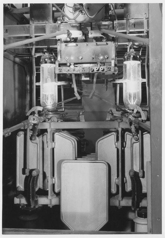
Electronic emission tube - 1000 Watts
"To my knowledge, only one of these amplifiers was installed in the field, in Dhaka, Bangladesh. One day, Geneva sent us a new super-beam antenna, 3 bands, 3 elements with traps. The maximum power supported was theoretically 1.5 kW. We then replaced our homemade quad antenna with this beam that shone in the sun. Connected to the new 1 kW amp, we had become pros. It must also be said that I was on my first mission and that I was too young to have a technical opinion.
After a few days, our amplifier showed signs of dissatisfaction. A measurement of the standing wave ratio showed that the antenna tuning was unacceptable. How to tell the great chef of Geneva that we had already toasted his wonder?
With the means on board, we replaced the defective beam by a wire butterfly antenna on 14 and 21 MHz which allowed us to continue the traffic.
A week later, Geneva asked us if we had any problems with this beam because they too had installed this same antenna and it had burned out. To our relief, we were then able to relate what had happened to us.
In fact this beam was intended for amateur radio traffic and did not support the kilowatt that we applied to it. We then replaced the traps with full size elements, which easily withstood this power which is not very common among radio amateurs."

Peter Kunz - HB9MCL
1000 Watts electronic emission tube - technical sheet:
This tube, installed in linear power amplifiers, especially at the Versoix station, amplified the output power of the transmitters (RF-controller) by a factor of ten (x 10). The transmission-reception switching was done by a pedal placed on the ground. When the Pactor was introduced it had to be replaced with automatic PIN diode switching.
- Triode with direct heating of the cathode
- Graphite anode
- 1000 Watts max output
- 4000 Volts of anode voltage
- Working frequency: 2-30MHz
- Automatic adjustment, controlled by the transmitter
This tube, installed in linear power amplifiers, especially at the Versoix station, amplified the output power of the transmitters (RF-controller) by a factor of ten (x 10). The transmission-reception switching was done by a pedal placed on the ground. When the Pactor was introduced it had to be replaced with automatic PIN diode switching.

Michel Vonlanthen - HB9AFO
